BASS AMPLIFIER LANEY DB400 is produce in 90s and it is uses for stage audio amplifier or bassist sound controll.
The Power Amplifier uses a symmetrical 55VDC supply voltage.
Table of Contents
What about amplifier look? TAKE A LOOK.
You can still increase this to 400 Watts if you increase the supply voltage for this power to 66 – 68 VDC symmetrically with a load of 4 Ohms.
Mathematically, if you want to make 1000 watts, the supply voltage must rise to 105VDC symmetrically. A number that you should not underestimate and certainly risky.
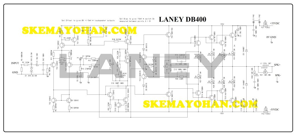
SCHEMATIC DIAGRAM OF BASS AMPLIFIER LANEY POWER SECTION
This is an edited schematic diagram of LANEY DB400.
Its a 4-step amplifier, starts from First transistor as pre-Amplifier to Final Power Amplifier.

DB400 Power Amplifier section is consists of blocks:
- Differential Preamplifier,
- Voltage Amplifier Stages,
- Servo Driver,
- Over Current Protection,
- Driver Amplifier,
- Final Power Amplifier.
There a Two trimpots inside the circuit are uses for DC-Ofsett and the other one is for idle Current of Final Power transistor.
Preamplifier is differential mode and uses SO692 transistors. TS2, TS6 (SO642) work as a Current Mirror.
GAIN of this BASS AMPLIFIER LANEY is devide factor of R16 by R15 or its about 37 times of GAIN.
Voltage Amplifier Stages Transistor using SO642.
It’s also using TS8 (SO692) as an active resistor as stabillized current source.
Servo Driver is using MPSA42 (TS12).
Using 4 pairs of transistors MJ15003 / MJ15004 which allows producing power dissipation up to 250 Watts per pair. This means transistor power capability can be up to 1000 Watts.
However, because the supply voltage is only up to 55 VDC, the power of 1000 Watts will not be achieved because it will only be able to reach about 272 Watts.
SEE ALSO
Other schematic Diagram inside this blog LOOK HERE.
Yohan’s blogspot for Audio Power and DIY check THIS LINK.
