OCL 120 WATTS LANEY EA120II

OCL 120 WATTS LANEY is a Guitar Power Amplifier with some feature such as Acoustic channels and Electro channels that you can choose one. For acoustic channels there are 6 Equalizer that can be used to evaluate the sound of your guitar.

INFO

See the pict HERE.

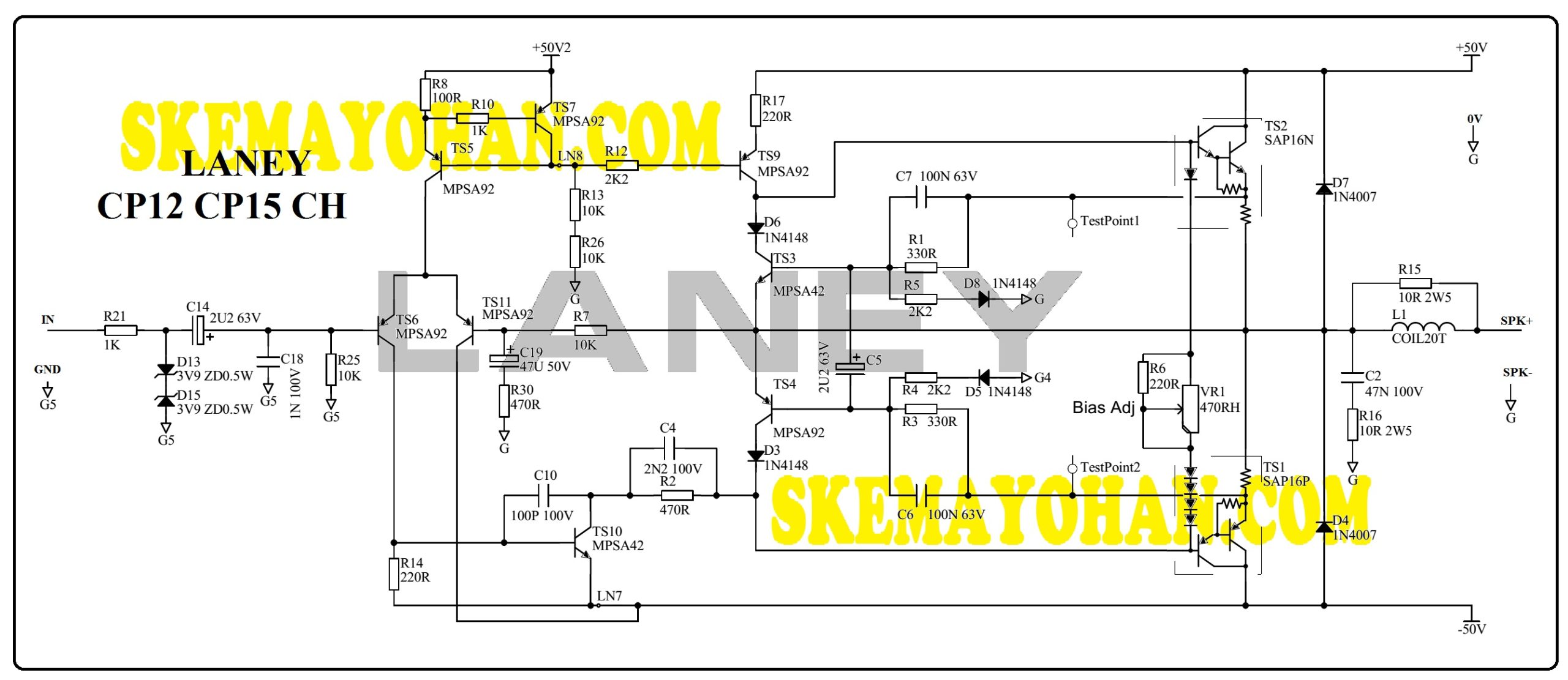
SCHEMATIC DIAGRAM POWER SECTION OF OCL 120 WATTS LANEY

This is an edited version of LANEY

OCL 120 WATTS LANEY

From the circuit above, its consists of some blocks:

  • Differential Preampifier,
  • Voltage Amplifier,
  • Servo Driver,
  • Over Current Protection,

At the input side, there is 3.9V Zener Diode available which is serves as an input signal limiter.

It also there is a 15VDC zener Diode as a voltage stabilizer for supply in this differential amplifier feed circuit.

GAIN of this circuit depends on the ratio of values between R11 and R12 or it’s about 100 times of gain.

The voltage amplifier T5 uses MPSA42.

The T6 servo driver uses BC 237 transistors where at the Base pin there is a 4K7 Trimpot which serves as a setting for idle current of the Final Power Transistors.

Its power amps also have the C5 elco booster capacitor which serves as positive feedback to mix in the voltage amplifier.

The OCP transistor here is uses BC237 paired with BC 307 (T7, T8).

This transistor has the task of if there is excess current in the R23 or R24, this will activate the T7 and T8 transistor bases to limit the signal to the power amplifier controller.

The amplifier driver here uses TIP31C and TIP32C pairs that have power capacities of up to 30 watts.

Finally, there are the T11 and T12 transistors that use TO-3 case, which is a quasi-pair that has a capacity of up to 150 watts.

NOTE FOR OCL 120 WATTS LANEY

By applying a voltage of 50 volts symmetrically, it is still possible for transistors to produce power up to 150 watts but at a load of 8 ohms.

When using a 4 ohm load, it is not recommended to do a full load for this amplifier because it is feared that overheating will occur when the signal is high level input.

Actually, you can modify this circuit by using another final transistor as long as it is a type of NPN.

For example, using a transistor 2sc 5200, even your voltage rises, there is no problem.

It’s just that you have to know the transistor calculation needed and how much supply voltage is needed too.

For example, this circuit is actually capable of up to 80 volts DC for supply, but you must have a final transistor of 5 or more pairs.

And the risk is that this power amplifier will output much more power but the current supply also requires more as well.

Final Power Transistor OCL 120 WATTS LANEY is using 2N3773 that can make power output up to 150 Watts (DATASHEETS). Below the transistor 2N3773:

SEE THE TRANSISTOR.

SEE ALSO

VARIOUS POWER AND Mixer Schematic Diagram inside this blog are LOOK HERE.

OCL 400W BASS AMPLIFIER LANEY

BASS AMPLIFIER LANEY DB400 is produce in 90s and it is uses for stage audio amplifier or bassist sound controll.

The Power Amplifier uses a symmetrical 55VDC supply voltage.

What about amplifier look? TAKE A LOOK.

You can still increase this to 400 Watts if you increase the supply voltage for this power to 66 – 68 VDC symmetrically with a load of 4 Ohms.

Mathematically, if you want to make 1000 watts, the supply voltage must rise to 105VDC symmetrically. A number that you should not underestimate and certainly risky.

SCHEMATIC DIAGRAM OF BASS AMPLIFIER LANEY POWER SECTION

This is an edited schematic diagram of LANEY DB400.

Its a 4-step amplifier, starts from First transistor as pre-Amplifier to Final Power Amplifier.

BASS AMPLIFIER LANEY pb400 schematic diagram

DB400 Power Amplifier section is consists of blocks:

  • Differential Preamplifier,
  • Voltage Amplifier Stages,
  • Servo Driver,
  • Over Current Protection,
  • Driver Amplifier,
  • Final Power Amplifier.

There a Two trimpots inside the circuit are uses for DC-Ofsett and the other one is for idle Current of Final Power transistor.

Preamplifier is differential mode and uses SO692 transistors. TS2, TS6 (SO642) work as a Current Mirror.

GAIN of this BASS AMPLIFIER LANEY is devide factor of R16 by R15 or its about 37 times of GAIN.

Voltage Amplifier Stages Transistor using SO642.

It’s also using TS8 (SO692) as an active resistor as stabillized current source.

Servo Driver is using MPSA42 (TS12).

Using 4 pairs of transistors MJ15003 / MJ15004 which allows producing power dissipation up to 250 Watts per pair. This means transistor power capability can be up to 1000 Watts.

However, because the supply voltage is only up to 55 VDC, the power of 1000 Watts will not be achieved because it will only be able to reach about 272 Watts.

SEE ALSO

Other schematic Diagram inside this blog LOOK HERE.

Yohan’s blogspot for Audio Power and DIY check THIS LINK.

OCL 160 WATTS LANEY CP12 CP15 CH

OCL 160 WATTS LANEY is came from LANEY CP12 CH OR LANEY CP15CH. It produce in 2000s and using as audio monitor for musician and general purpose in the stage.

This is the IMAGE of THIS MONITOR.

SCHEMATIC DIAGRAM OCL 160 WATTS LANEY

Power amplifier schematic diagram of this guitar amps is quite simple. It just uses cheap MPSA92 and MPSA42 transistors and final output using Darlington SAP16N/ SAP16P.

Just take a look like pic below:

OCL 160 WATTS LANEY CP12 CP15 CH schematic diagram

All resistors are 1/2 Watt except resistors for Zobel Network R16 and R15 (2W).

All working voltages of capacitors and elco are 50V and 63Volt.

The supporting components of this circuit use MPSA92 transistors for NPN and MPSA42 for PNP.

The supply voltage uses 50VDC symmetrical.

The circuit consists of some blocks:

  • Preamp Differensial
  • Voltage Amplifier Stages
  • Over Current Protection
  • Darlington Amplification

This preamplifier has a GAIN of up to 20x by looking at the R7:R430 value comparison.

Final output transistor uses SAP16N/P number which has dissipation capability up to 160 Watts.

With a voltage of 50 Volts it will be possible to produce 160 Watts of power at a load of 4 Ohms.

SEE ALSO:

Another Power Amplifeir Schematic inside this blog LOOK HERE.

Yohan’s Blogspot audio and preamp THIS LINK.

OCL 250 WATTS LANEY CP12

LANEY CP12 is an OCL 250 WATTS LANEY, an Amplifier Monitor made by LANEY that it is using symmetrical 52 VDC and MJ15003/MJ15004 TO-3 transistor as Final Power Amplifier.

In the brochure they said that its design for a 120 Watts Power Amplifier even though it uses 250 watts transistors.

INFORMATION ABOUT THE MONITOR

Inside a CP12 LOOK HERE.

From: Outback Electrical NZ

SCHEMATIC DIAGRAM OCL 250 WATTS LANEY POWER SECTION

The following is a schematic diagram of the Power amplifier section of the LANEY CP12 after editing:

OCL 250 WATTS LANEY CP12 SCHEMATIC DIAGRAM

From this circuit OCL 250 WATTS LANEY we can find out if it consists of several blocks, including:

  • Differential Preamplifier,
  • Voltage Amplifier Stages,
  • Servo Driver,
  • Over Current Protection,
  • Driver Amplifier, dan Lastly is
  • Final Power amplifier.

Final power transistor use MJ15003 / 04 and this is able to make 250 Watts audio Power output.

SEE ALSO

Another schematic Diagram Power Amplifier inside this blog please READ HERE.

VIDEO

Concept CP12 Repair by Outback Electrical NZ

OCL 300 WATTS LANEY

OCL 300 WATTS LANEY CK300 is a Power amplifier made by Laney era 2000s that uses the SAP15 transistor module as the Final Power Amplifier.

A symmetrical 60 Volt voltage and 2 pairs of Final transistors are possible to produce audio up to 300 Watts at a 4 Ohm load.

The CK 300 is a 4-channel microphone amplifier with a power amplifier inside. It’s like a 4-channel mixer with a power amplifier but in one package.

Need to know the unit? SEE THIS LINK.

SCHEMATIC DIAGRAM OF OCL 300 WATTS LANEY

This is the result of edited schematic diagram of LANEY’s CK300 Power Amplifier:

edited OCL 300 WATTS LANEY

This Amplifeir power circuit consists of several blocks:

  • Differential Preamplifier,
  • Voltage Amplifier Stages,
  • Over Current Protection,
  • Darlington Amplifier.

This amplifier has two trimpot for setting in DC-Ofset and Idle Current for the Final Power Transistor.

GAIN of the amplifier is depending on comparing value of R116 with R115.

Final Power Transistors use SAP15N SAP15P pairs, each of which has a power dissipation capability of up to 150 Watts (DATASHEETS).

SEE ALSO

Various Power Amplifier schematic diagram inside this blog please READ HERE.

SKEMA POWER MARCOPOLO MC-158

Seorang teman bertanya kepada saya apakah saya memiliki skema Power Marcopolo? Tentu saya bilang tidak punya karena saya memang tidak memilikinya.

Kemudian saya mencoba mencari di internet dan memang belum ada skema Power Karaoke merk ini.

Setelah mencoba melihat-lihat fitur Power Mixer Karaoke ini, maka saya mencoba untuk mengobservasi rangkaian Power Amplifiernya saja.

INFO

MARCOPOLO MC 158 memiliki fitur antara lain adalah:

  • 4 input Microphone. Cocok untuk karaoke rumah maupun meeting room.
  • Effek audio
  • SD Card input
  • Bluetooth
  • Radio Fm
  • 2 grup kanal equalizer, masing-masing adalah 8 kanal frekwensi.

dan banyak fitur audio lainnya

HARGA POWER MARCOPOLO

Pada saat artikel ini saya ketik, harga power karaoke MARCOPOLO ini berkisar mulai 700 ribu hingga 1,3 juta.

Berikut adalah toko online yang menjual power karaoke ini di bawah harga 1 juta:

BAHAN OBSERVASI

Gambar di bawah ini adalah hasil tangkapan layar pada saat saya mempelajari rangkaian power pada ampli MARCOPOLO ini.

Dari gambar di atas selanjutnya saya lakukan tracing rangkaian.

TRACED SCHEMATIC DIAGRAM SKEMA POWER MARCOPOLO

Berikut adalah hasil terjemahan gambar jalur dan posisi komponen pada seksi Power Ampifier pada mixer karaoke MARCOPOLO ini:

HASIL TRACING SKEMA POWER MARCOPOLO

Note: Skema bisa saja salah dalam penentuan value maupun salah jalur. Saya hanya mengandalkan kaidah Prinsip power Amplifier dan observasi pada video tayangan pada youtube. Kritik dan saran sangat diperlukan.

Rangkaian power amplifier adalah lumayan sederhana.Hanya menggunakan 7 transistor daya kecil dan satu pasang transistor Daya.

Tegangan simetris yang 32 Volt ini menghasilkan daya maksimum sebesar 90 Watt pada beban 4 Ohm.

SIMULASI

Selanjutnya hasil tracing skema ini saya lakukan pengetesan untuk memastikan apakan gambar saya ini telah sesuai dengan kaidah Power Amplifier.

Hasil simulasi adalah seperti di bawah ini:

SIMULASI PADA SKEMA POWER MARCOPOLO

Pada tegangan input 1,3Volt Vp-p berfrekwensi 1kHz, maka akan mampu menghasilkan tegangan output hingga 28Vp atau 19 Vac

SUMBER VIDEO:

amplifier marcopolo mc-158 tidak keluar suara by TEKNISI UNIVERSAL JOGJA

SKEMA POWER GENOVA FC-A5200

Tulisan ini tentang SKEMA POWER GENOVA yang saya dapat pada saat melihat-lihat review macam-macam power di internet.

GENOVA dengan nomer seri FC-A5200 sepertinya mirip dengan power amplifier merk FIRST CLASS, akan tetapi saya belum bisa menjelaskan detailnya.

Saya hanya penasaran saja bagaimanakah gaya rangkaian Power Amplifier ini.

INFO

Penampakan Power adalah seperti LIHAT LINK INI. Pabrik menyatakan pada tulisan belakang casing bahwa ia mengeluarkan daya hingga 90W x 2 atau total daya 180 watt.

SKEMA POWER GENOVA

Di bawah ini adalah hasl tangkapan layar PCb sisi belakang power untuk bahan tracing.

PCB JALUR SKEMA POWER GENOVA

Selanjutnya saya lakukan observasi tata letak komponen ini .

SKEMA POWER GENOVA HASIL TRACING

Berikut ini adalah skema hasil tracing atas Power kit pada PCB Power ini:

SKEMA POWER GENOVA HASIL TRACING

Di sini bisa kita ketahui bahwa rangkaian ini terdiri dari beberapa blok, yaitu:

  • Preamplifier differensial,
  • Penguat Tegangan,
  • Servo Driver,
  • Driver Amplifier, dan Final Power

Transistor Final Power memiliki kemampuan dissipasi hingga 100 Watt (DATASHEETS).

Jika kita melihat tegangan 40VDC simetris ini maka bisa menghitung bahwa kemampuan daya 90 Watts sesuai catatan pabrik adalah pada beban 8 Ohm.

SIMULASI

Untuk memastikan rangkaian ini bekerja dengan baik secara kaidah elektronika, maka hasil gambar ulang ini saya coba untuk lakukan simulasi.

Simulasi menggunakan signal Generator 1kHz dengan sinyal 1,3VAC.

Hasil simulasi adalah rangkaian ini bekerja dengan baik dengan hasil tampilan oscilloscope adalah 38Vp atau 36Vp-p pada tanpa beban.

Dengan memberi beban 8 Ohm juga tidak ada masalah namun tegangan output menjadi 25Vp.

SKEMA POWER GENOVA SIMULASI

Dengan demikian gambar skema ini sudah benar secara teori. Hasil sesungguhnya tetap pada anda sendiri sebagai pembuat power amplifier ini.

SEE ALSO

Skema Power lainnya dalam blog ini BACA SINI.

Blogspot Yohan berisikan macam-macam skema Power Amplifier LINK INI.

Blog dotcom aneka macam skema Power Amplifier Audio dan Mixer Built Up CEK LINK INI.

VIDEO YOUTUBE:

by PONIMAN

OCL 80 WATTS LANEY CK80

I got OCL 80 WATTS LANEY CK80 when browsing the internet when searching for LANEY Keyboard Amplifiers.

And I think 80 Watts is enough to filling a little room or small venue when you show your musical skills or to entertain your audience.

But in this article, I just try to review the schematic diagram of this amplifier only.

INFO

SEE the AMPLIFIERS.

Its support 1 Microphone input and 2 of line inputs. For microphone input it has GAIN control also Two Pots of Tone Control.

CK80 only using a single Load-Speaker. It only 15″ and good enough to roar.

SCHEMATIC DIAGRAM OCL 80 WATTS LANEY CK80

The image below shows an edited schematic diagram of CK80 by LANEY:

OCL 80 WATTS LANEY CK80 SCHEMATIC DIAGRAM

The amplifier working in 50 Volts DC Symmetrical Supply Voltage. When the load is 8 Ohm, It’s possible to reaching 150 Watts or 250 watts at 4 Ohm load on output terminals.

This circuit does not have a trimpot for Dc-Offset but it has a trimpot for Servo Driver.

The Servo Driver here is on the TS1 transitor (BC237).

OCP transistor are TS7 and TS8. Its working as current limiter for final output transistor.

Any over current flow via resistor R49 and R50, the OCP will work as well.

This final power amplifier uses a quasi-technique, where the final transistor uses only one type. This circuit only uses NPN type transistors.

TIP35C transistor is a transistor with TO218 packaging that has a power dissipation capability of up to 125 Watts.

SEE ALSO

Another Audio Power Amplifier inside this blog LOOK HERE.

Blogspot of YOHAN AUDIO LINK HERE.

OCL 165 WATTS LANEY

I found OCL 165 WATTS LANEY from service manual of guitar amplifier CK165 series.

It uses a pair of Darlington Transistors and there is internal driver transistor and signal diode inside.

It uses 50 Volts symmetrical voltage to supply the circuit. And it also using Transistor SAP16 that is an audio purpuse to make audio output up to 160 watts at 4 Ohms load.

INFO OCL 165 WATTS LANEY CK165

LANEY CK165 is mini powered mixer. It has 4 channel inputs and it has Four potensio to control each channel.

It uses 15″ speaker for make bass frequency looks better.

You can find the price and info of this Amps by looking for JACOB MUSIC or YUSRUS.

SCHEMATIC DIAGRAM OF LANEY CK165

The picture below is an edited from the original schematic.

OCL 165 WATTS LANEY schematic diagram

The amps has a Trimpot at a Preamplifier Block to make the output always Zero VDC. It also called with DC-Ofset.

TS10 is a Voltage Amplifier Stages. Its amplify the input signal and make it bigger voltage.

The current through VCC 50V, R17, TS9, VR1, internal Diode of SAP transistors, and R2.

Over Current Protection here uses transistors TS3 and TS4 (MPSA42 and MPSA92).

When the output current passing through resistors R19 and R20 are exceeds 0.7 VDC then its OCP transistor will doing work as well and it will reduce the voltage supply to the Base transistor SAP16N/P so that this will reduce the output current to the load.

No Driver transistors needed. The SAP16 transistors already contains an internal transistor driver inside.

This OCL 165 WATTS LANEY power amplifier does not use a Servo Driver. It only utilizes the internal diode inside the SAP16P module and there is only the addition of a Timpot to limit the idle current in the Final Output.

SEE ALSO

Another Audio Power Amplifier inside this blog LOOK HERE.

Blogspot of YOHAN AUDIO LINK HERE.

OCL 250 WATTS LANEY

OCL 250 WATTS LANEY mean from an audio Amplifier especially for guitar or keyboard player brand LANEY BC250 series.

It uses two pairs of MJ150003/04 transistor and it mean that this power amps able to make audio output up to 500 Watts.

But its only be 250 Watts because the Power Supply of the Amps is only 50 Volts simmetrically.

INFO

Appearance of the amps is like LOOKS LIKE THIS.

Feature:

  • 5 channels graphic equalizer.

Power Supply for Power Amplifier need 50VDC simetrically.

How price? Check RAHMAN MUSIK

SCHEMATIC DIAGRAM OCL 250 WATTS LANEY

This is an edited schematic diagram of LANEY BC250 guitar Power Amplifier section:

OCL 250 WATTS LANEY schematic diagram

From this picture we can see if this power amplifier circuit consists of several block:

  • Differential Preamplifier with Current Mirror
  • Voltage Amplifier Stages,
  • Servo Driver,
  • Driver Amplifier, and lastly is
  • Final Power Amplifier

Available trimpot for DC offset setting

The GAIN of this circuit depends on the ratio the value of R16 to R15 or its 37 times.

Final Power amplifier using MJ15003/ 15004 that it can be 250 Watts output (DATASHEETS). This amps uses 2 pair of it.

By 50 Volts of symmetrical supply, its able to make 225 Watts at terminal output at 4 Ohm load.

SEE ALSO

Another Audio Power Amplifier inside this blog LOOK HERE.

Blogspot of YOHAN AUDIO LINK HERE.

Various Built Up Power and Mixer Schematic Diagram at YOHAN INDRAWIJAYA COM.