
OCL 160 WATTS LANEY is came from LANEY CP12 CH OR LANEY CP15CH. It produce in 2000s and using as audio monitor for musician and general purpose in the stage.
This is the IMAGE of THIS MONITOR.
Table of Contents
SCHEMATIC DIAGRAM OCL 160 WATTS LANEY
Power amplifier schematic diagram of this guitar amps is quite simple. It just uses cheap MPSA92 and MPSA42 transistors and final output using Darlington SAP16N/ SAP16P.
Just take a look like pic below:
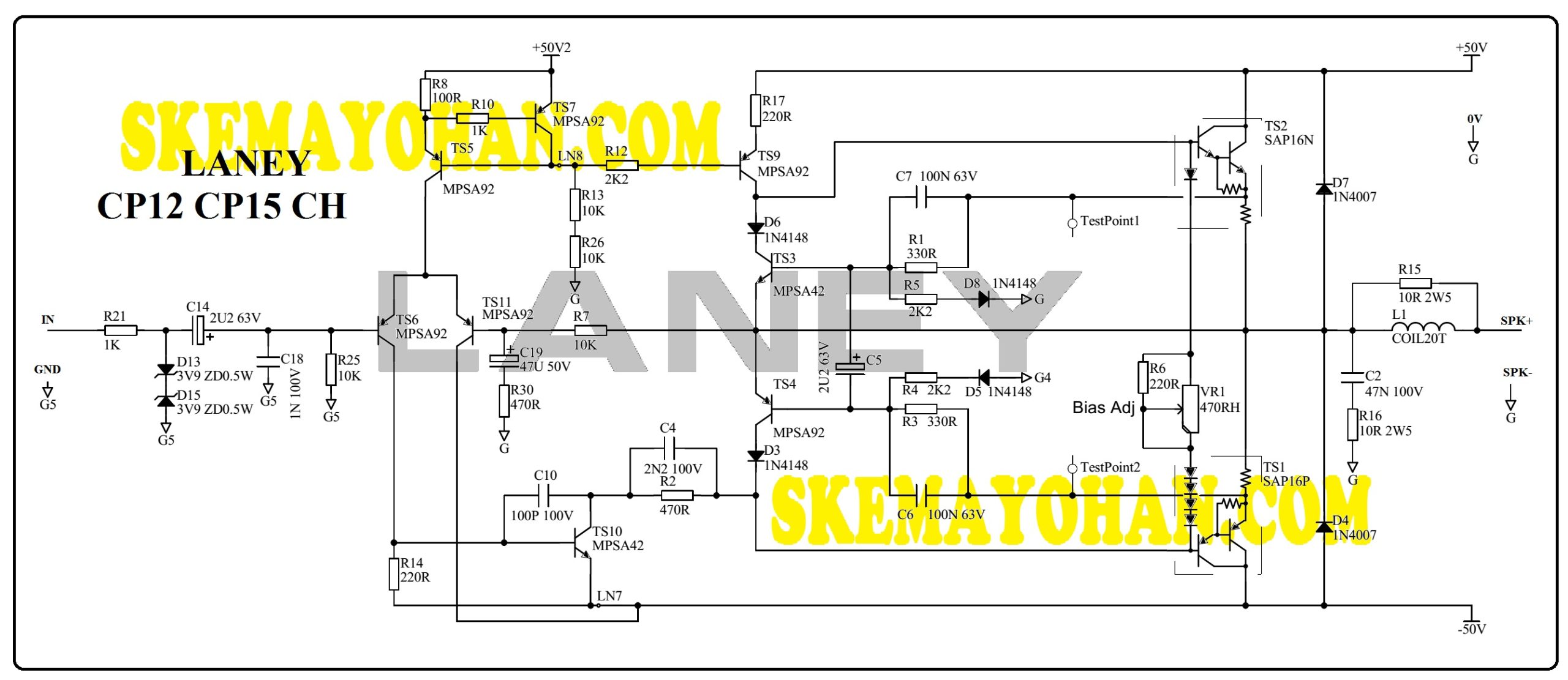
All resistors are 1/2 Watt except resistors for Zobel Network R16 and R15 (2W).
All working voltages of capacitors and elco are 50V and 63Volt.
The supporting components of this circuit use MPSA92 transistors for NPN and MPSA42 for PNP.
The supply voltage uses 50VDC symmetrical.
The circuit consists of some blocks:
- Preamp Differensial
- Voltage Amplifier Stages
- Over Current Protection
- Darlington Amplification
This preamplifier has a GAIN of up to 20x by looking at the R7:R430 value comparison.
Final output transistor uses SAP16N/P number which has dissipation capability up to 160 Watts.
With a voltage of 50 Volts it will be possible to produce 160 Watts of power at a load of 4 Ohms.
SEE ALSO:
Another Power Amplifeir Schematic inside this blog LOOK HERE.
Yohan’s Blogspot audio and preamp THIS LINK.

